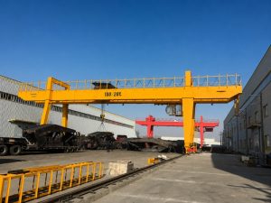
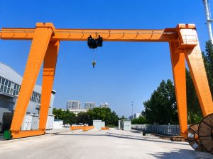
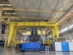
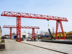

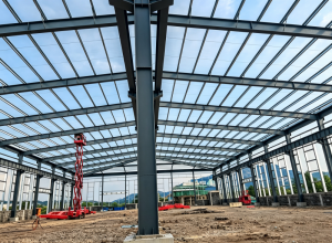
Factory-Direct Supply
No trading intermediaries—customers work directly with our factory for selection, customization, production coordination and support.





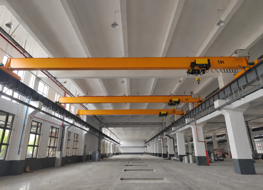
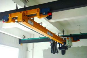
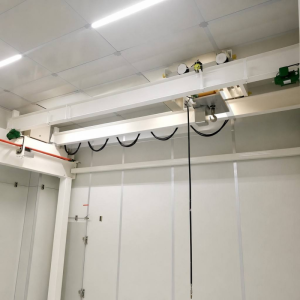
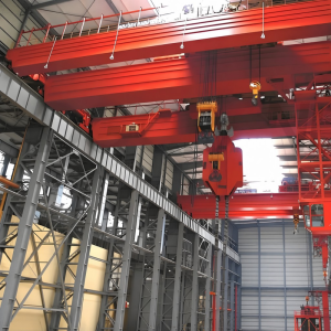
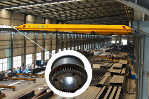
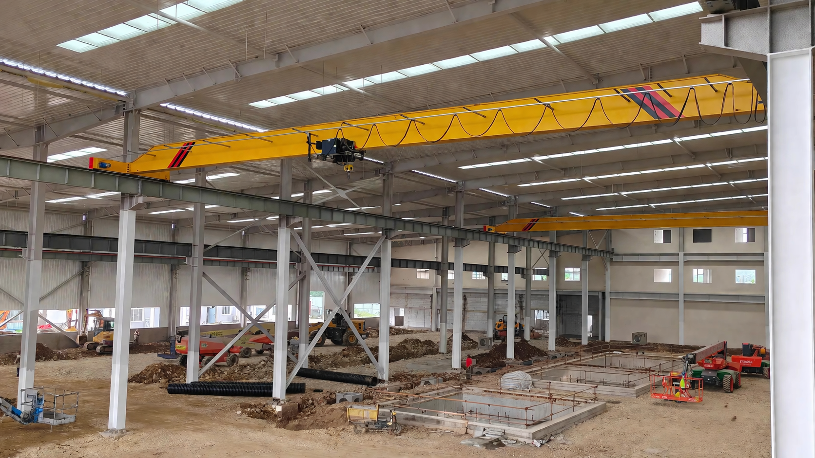
Independently developed using advanced European crane design and manufacturing technology, our FEM standard overhead crane combines a clean, modern appearance with efficient and reliable material handling performance.
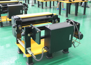
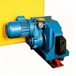
The travelling mechanism uses an integrated three-in-one drive unit with a hardened-gear reducer, variable-frequency brake motor and compact braking system. It delivers smooth acceleration and deceleration, precise positioning, low noise and dependable operation for demanding industrial applications.
Overview
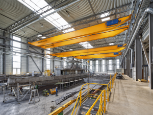
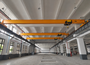
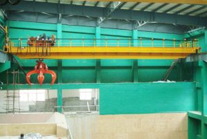
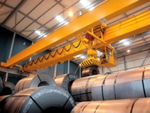
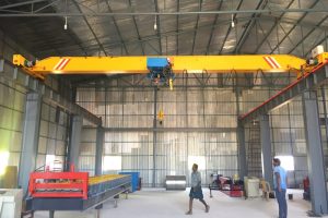
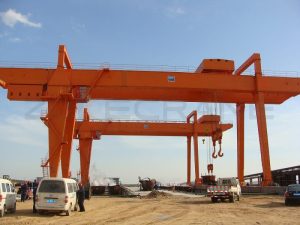
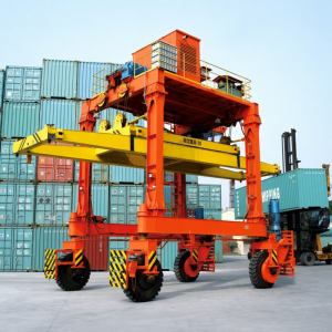
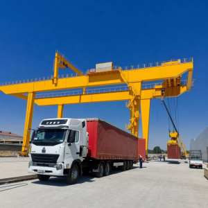
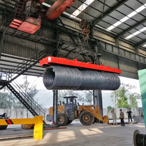
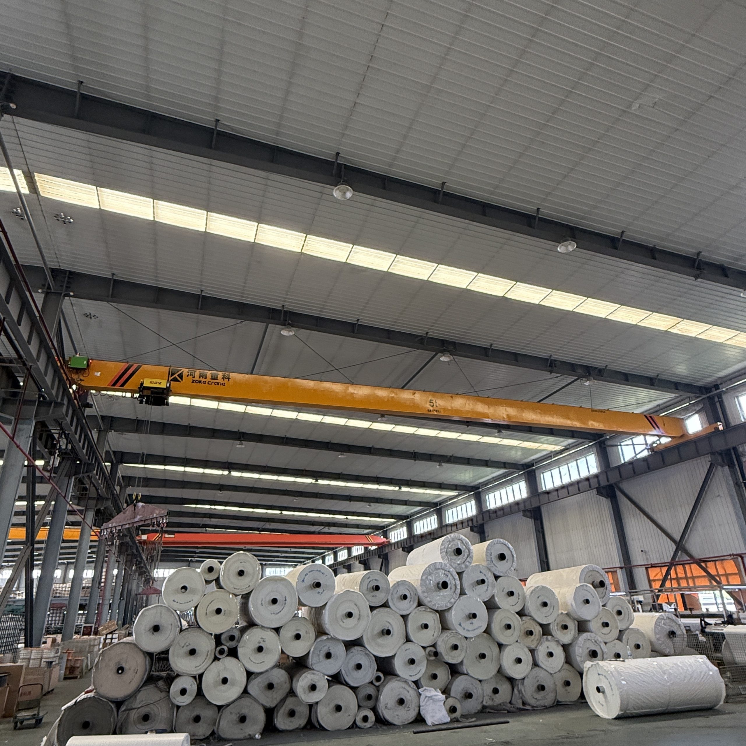
European-type single-girder overhead cranes are engineered for efficient material handling in workshops and warehouses across machinery manufacturing, petroleum and petrochemical, ports, railways, civil aviation, power, food processing, paper, building materials, electronics and other industries. They are particularly well suited to operations that demand accurate load positioning and the precision assembly of large components.
Modular design, variable-frequency speed control and automatic monitoring provide smooth, precise and dependable movement. Integrated safeguards—including overload, overcurrent and voltage-loss protection—help deliver reliable performance throughout demanding production cycles.
Why Choose ZOKE
Factory-direct engineering, controlled production and application-specific protection deliver reliable cranes configured for each project.
No trading intermediaries—customers work directly with our factory for selection, customization, production coordination and support.
Design, production and inspection follow applicable FEM and GB requirements and the confirmed project specification.
Experienced engineers and a dedicated testing team verify the crane configuration and performance before shipment.
Good rigidity, easy operation, low noise and an efficient footprint help save plant space and investment.
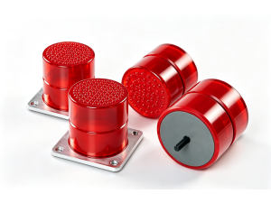
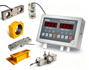
Overload and lifting-height limit switches, PU anti-collision buffers for crane travel, and overcurrent, low-voltage and power-failure protection support safer operation.
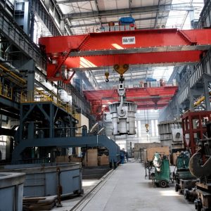
Standard motors use IP44 protection with Class F insulation. Explosion-proof and metallurgical configurations are available with suitable Ex ratings, Class H insulation, heat-resistant cables and thermal barriers.
Sandblasting can be applied to materials or finished products, followed by epoxy zinc-rich primer and a chlorinated-rubber topcoat for durable corrosion resistance.
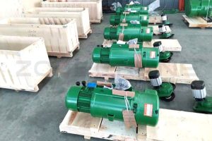
Wooden cases or waterproof wrapping protect equipment according to its size and transport requirements.
Main Girder Comparison
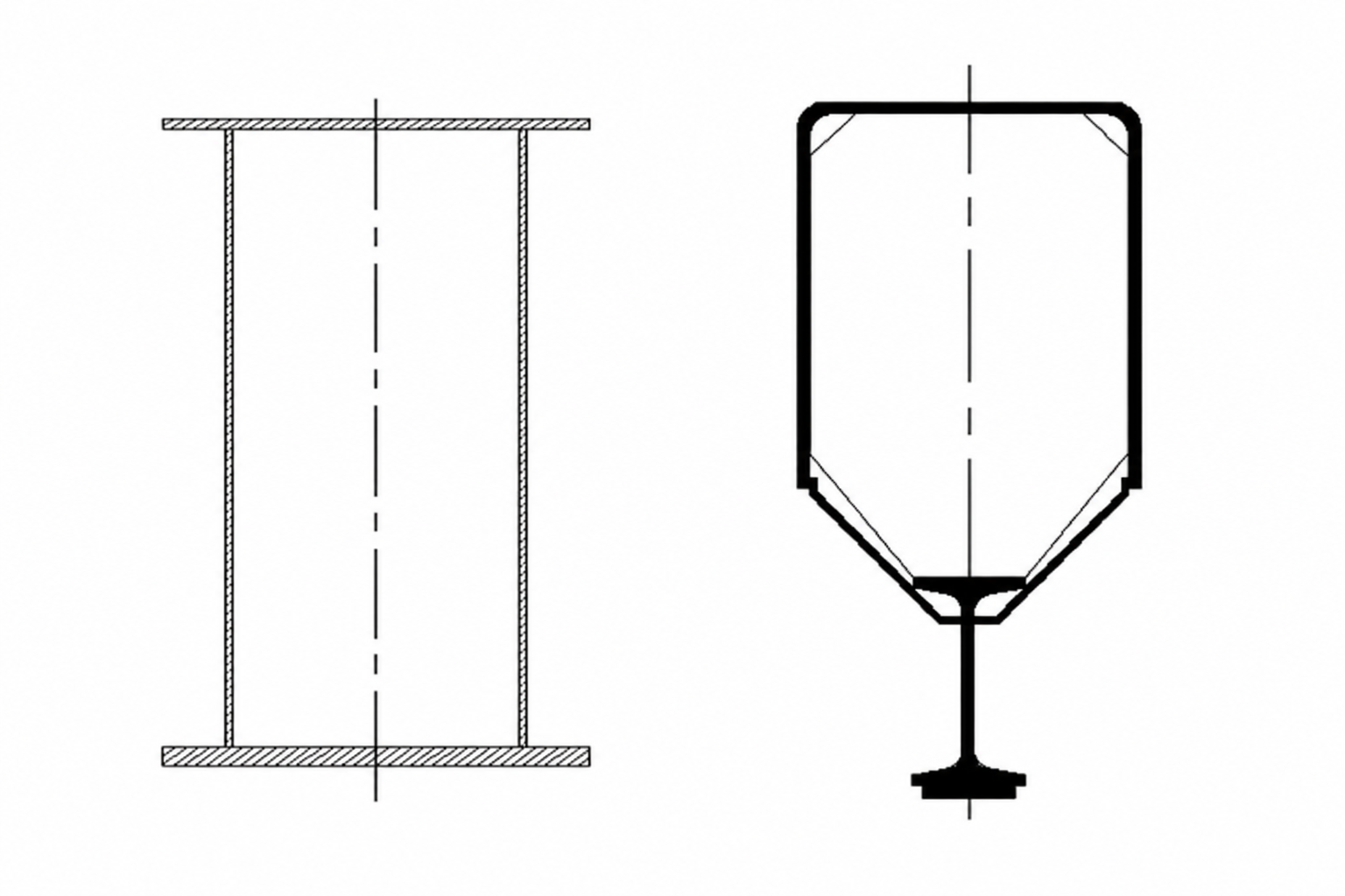
Both designs are proven solutions for workshops and warehouses. The key difference is how the main girder and hoist travelling track are integrated, which affects rigidity, deadweight and space utilization.
| Comparison | FEM Single-Girder Crane | Conventional Single-Girder Crane |
|---|---|---|
| Main Girder | Optimized welded box-section structure designed as an integrated load-bearing member. | Main girder is commonly combined with a separate I-beam running track underneath. |
| Hoist Trolley Track | Trolley wheels travel on the engineered lower flange of the box girder. | Electric hoist trolley travels on the lower flange of the suspended I-beam. |
| Rigidity & Load Distribution | High bending and torsional rigidity with efficient, uniform load transfer. | Mature and reliable construction, with performance determined by the girder and I-beam combination. |
| Deadweight | Optimized sections can reduce crane deadweight and wheel loads for the same duty requirements. | Generally uses more structural material and may produce higher deadweight and wheel loads. |
| Space Utilization | Compact integrated geometry supports better use of workshop height and building space. | The separate I-beam track increases structural depth and may require more installation space. |
Choose the right configuration
Click each component to view its construction, function and standard configuration.
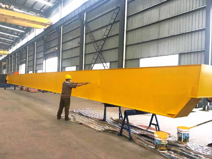
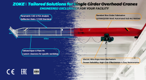
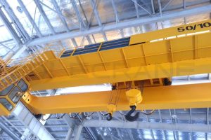
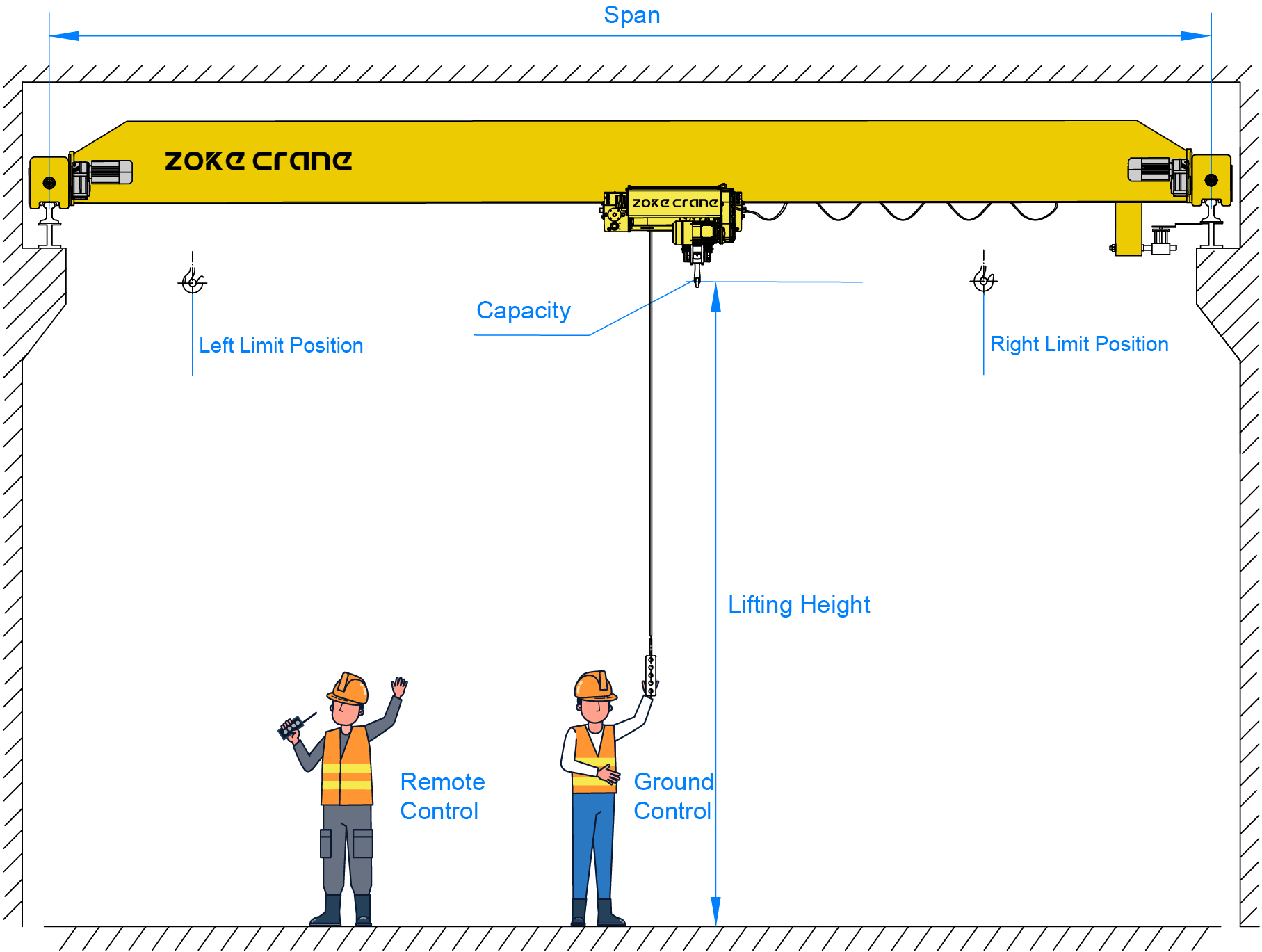
The main girder uses a welded box-section structure engineered for the required capacity, span and duty class. Its optimized cross-section combines high rigidity with reduced deadweight, while precision cutting and controlled welding support dimensional accuracy and stable crane travel.
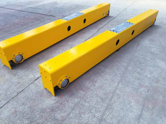
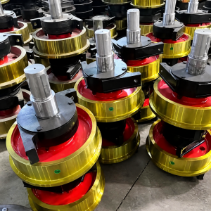
Compact box-section end carriages integrate machined wheel sets, buffers and modular connections. The wheelbase and rail gauge are matched to the runway system to provide accurate alignment, balanced load distribution and dependable long-travel performance.
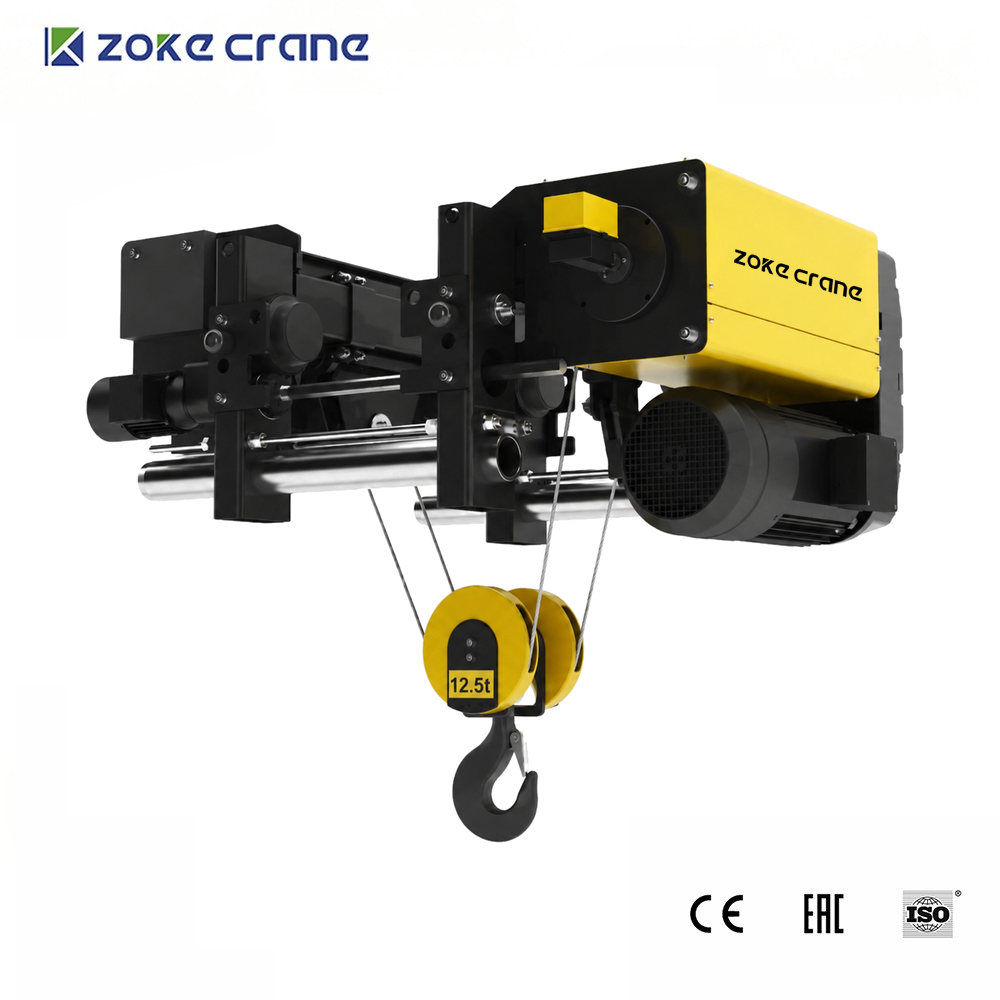
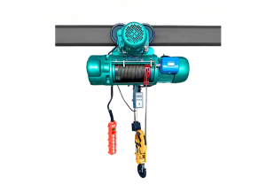
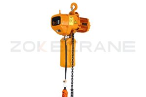
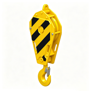
The FEM wire-rope lifting mechanism combines the lifting motor, hardened-gear reducer, rope drum, rope guide and hook block in a compact arrangement. Lifting speed, reeving and safety devices are selected according to the rated load, lifting height and operating duty.
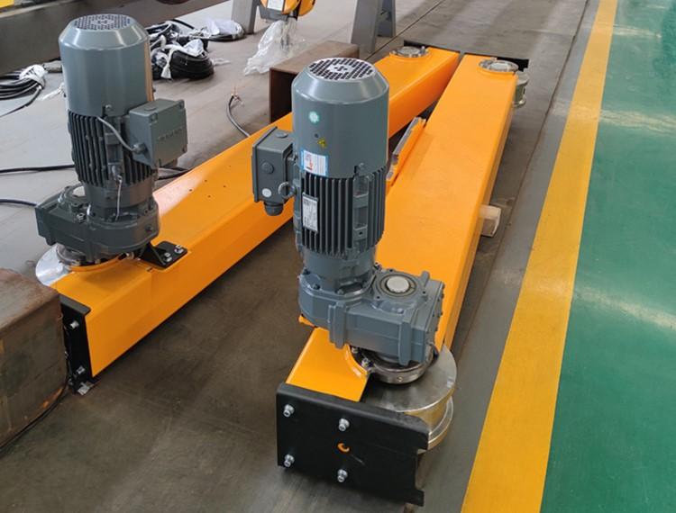
The integrated traveling drive combines a motor, hardened-gear reducer and brake in one compact unit. Variable-frequency control provides smooth acceleration and deceleration, synchronized bridge travel, precise positioning and reduced mechanical impact.
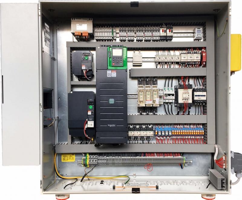
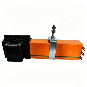
The modular electrical system is designed for clear wiring, reliable protection and convenient maintenance. Standard safety functions can include overload, overcurrent, phase-loss, undervoltage, emergency-stop and travel-limit protection, with the final configuration matched to project requirements.
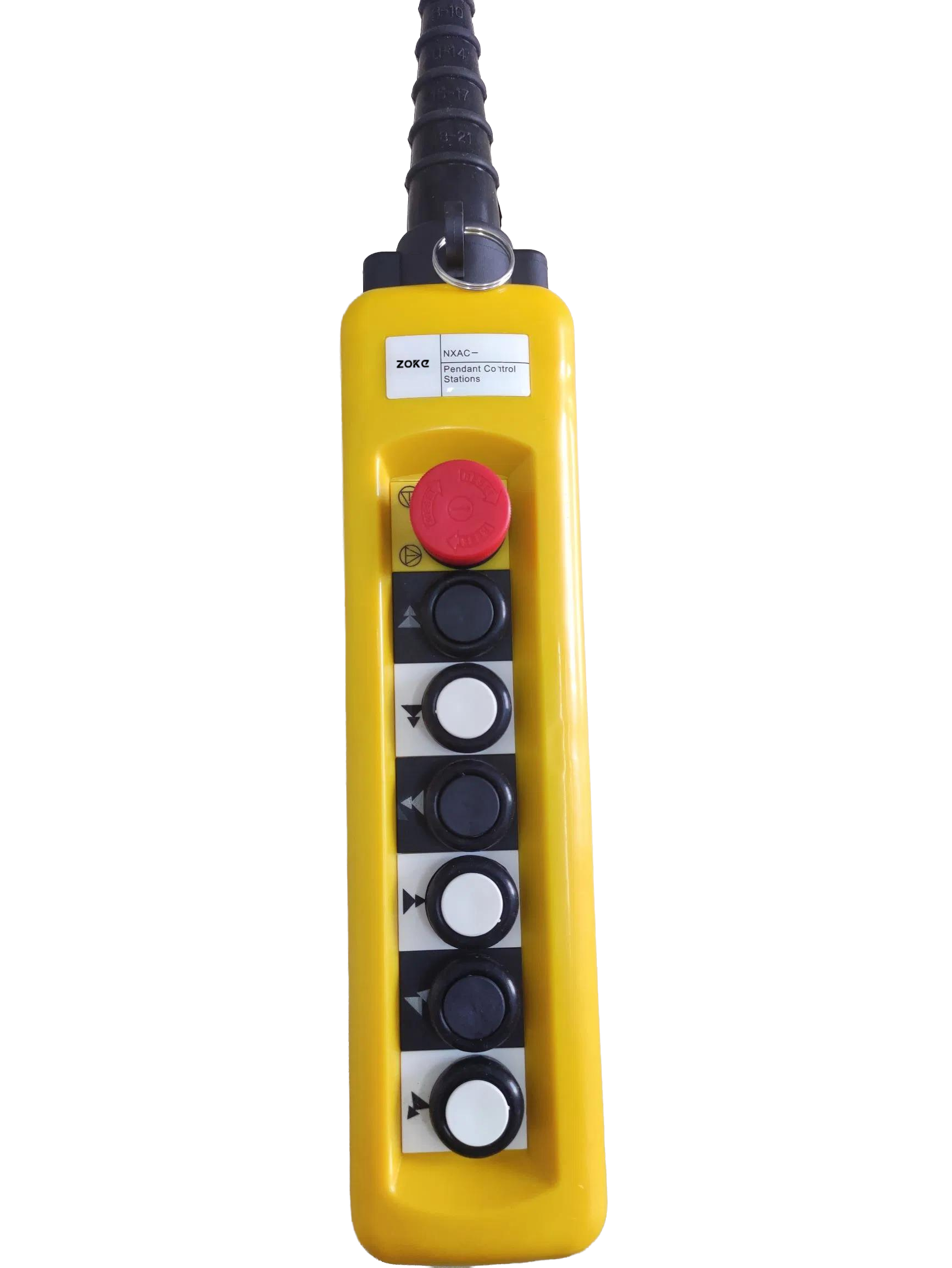
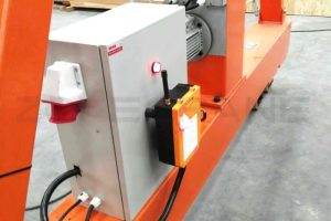
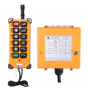
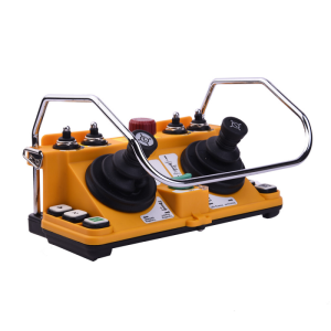
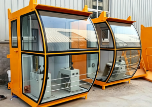
Pendant control and wireless remote control are available for flexible operation from a safe working position; cabin control can be supplied when required. Button layout, control voltage and emergency-stop functions are configured for the application and local operating practice.
FAQ
Please provide the rated capacity, span, lifting height, runway length, power supply, duty requirements, operating environment and the material to be handled.
Yes. The span, lifting height, runway arrangement, travelling speed and power supply can be engineered for the site. Pendant control, wireless remote control and cabin control are available according to the project.
Typical protection includes overload protection, upper and lower lifting limits, crane travel limits, PU anti-collision buffers, emergency stop, phase-loss and undervoltage protection. The final configuration is confirmed for each application.
Key structures, mechanisms, electrical controls, brakes and safety devices are inspected and tested before shipment. Test records, operating documents and export packaging can be supplied according to the contract.
The latest ZOKECRANE price list, news, articles, and resources.