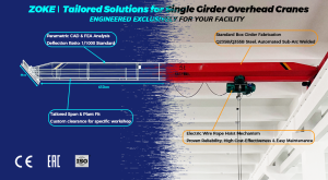
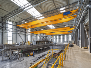
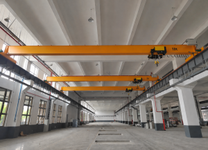
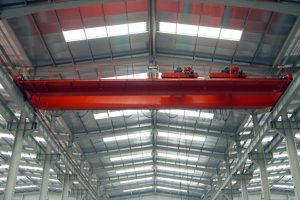
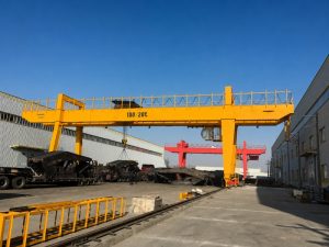
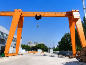
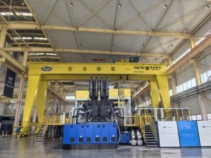
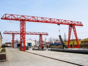

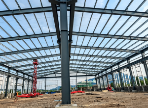
Simple, Rigid Structure
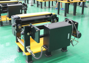
Compact construction provides good rigidity and stable performance while keeping transport, installation and routine maintenance straightforward.





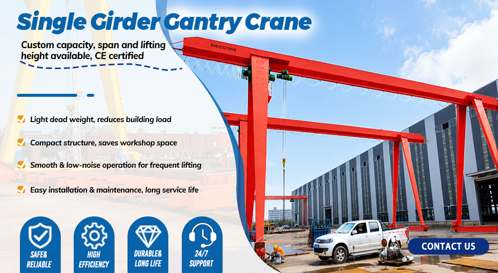
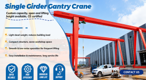
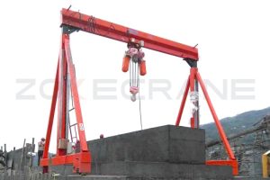
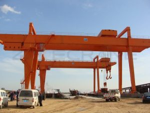
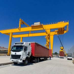
Single girder gantry cranes are self-supporting and are not restricted by existing workshop steel structures, making them easy to install and adaptable to factories, warehouses, ports, mines and outdoor yards.
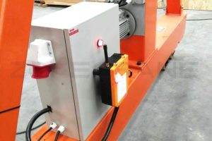
Built with a welded box-girder frame, support legs, a crane travelling system, electric hoist and control panel, the crane provides high strength, good rigidity and stable operation for loads from 0.5 to 20 tonnes. Power can be supplied by cable or conductor line, with pendant, wireless remote or cabin control available.
Configurations can be engineered for limited headroom, FEM-standard European design, truss construction for reduced wind load and cost, or semi-gantry layouts where runway support is available on one side.
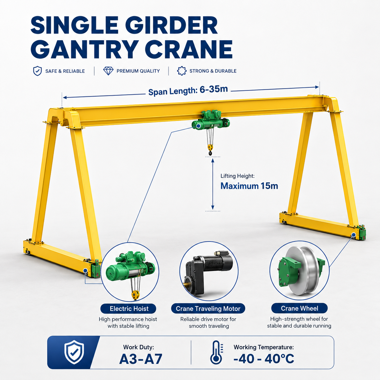
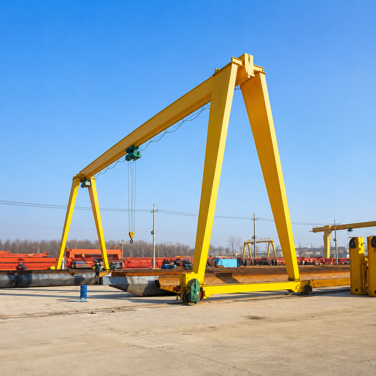
Electric hoist gantry cranes are designed and manufactured in accordance with applicable crane standards, including GB/T 3811-2008 and JB/T 5663-2008. Their self-supporting structure provides a practical lifting solution where an existing workshop runway is unavailable or unsuitable.
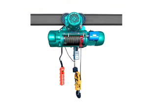
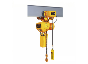
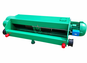
CD/MD electric wire rope hoists or electric chain hoists can be selected as the lifting mechanism. Composed of the steel gantry, crane travelling mechanism, hoist and electrical control system, the crane is suitable for factories, warehouses, freight yards, docks and construction sites, with capacity, span, lifting height and controls engineered for the project.
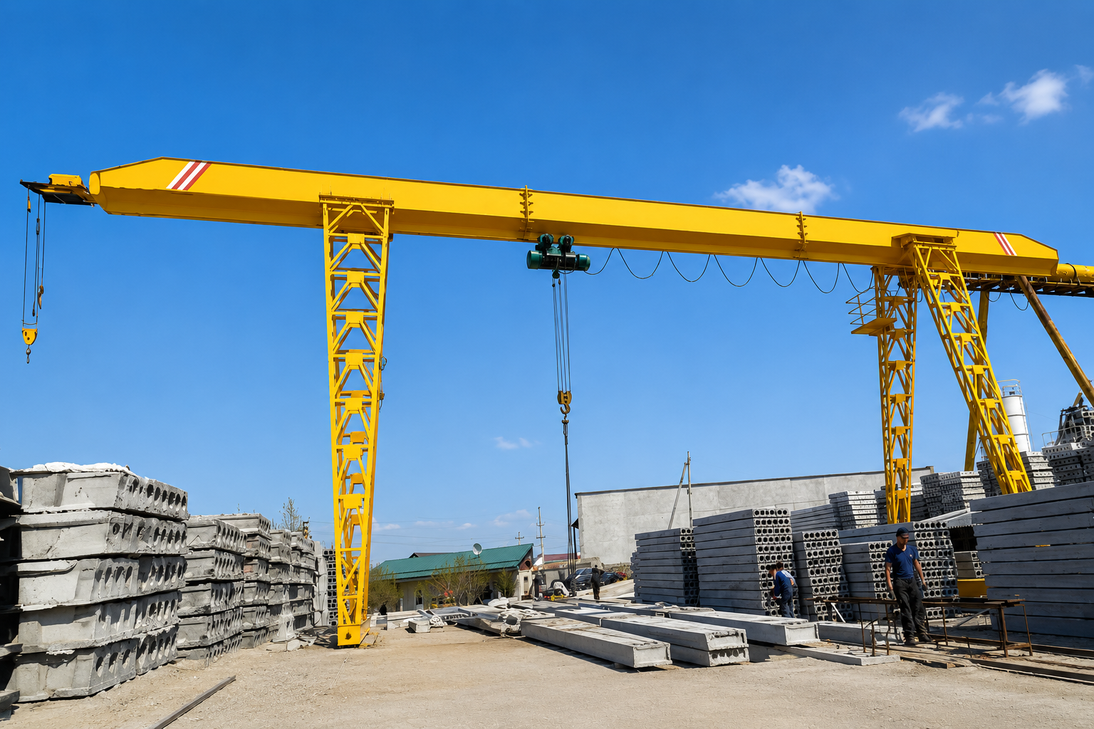
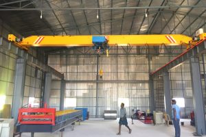
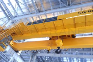
The MH single girder gantry crane combines structural rigidity, steady operation and practical safety protection with application-specific engineering for indoor and outdoor lifting.
Compact construction provides good rigidity and stable performance while keeping transport, installation and routine maintenance straightforward.
Work directly with the manufacturer for selection, drawings, production follow-up and technical support. Warranty terms of 12 or 18 months can be confirmed with the contract.
Professional engineering and testing teams manufacture to the confirmed GB or FEM requirements, with inspection before shipment.
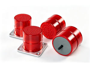
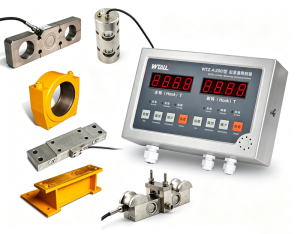
Overload limiting, upper and lower lifting limits, PU travel buffers, low-voltage protection and power-failure protection help safeguard operation.
Standard motors use IP44 protection and Class F insulation. Explosion-proof or metallurgical configurations can be engineered for special environments.
Sandblasting, epoxy zinc-rich primer and a protective topcoat improve durability. Wooden cases or waterproof wrapping protect the crane during shipment.
Click each component to view its function and standard configuration.
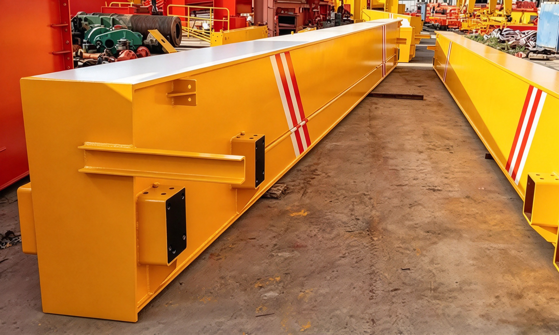
The main beam is a welded steel load-bearing structure engineered for the rated capacity, span and duty class. Its box or profile design provides the rigidity required for stable hoist travel and controlled load handling.
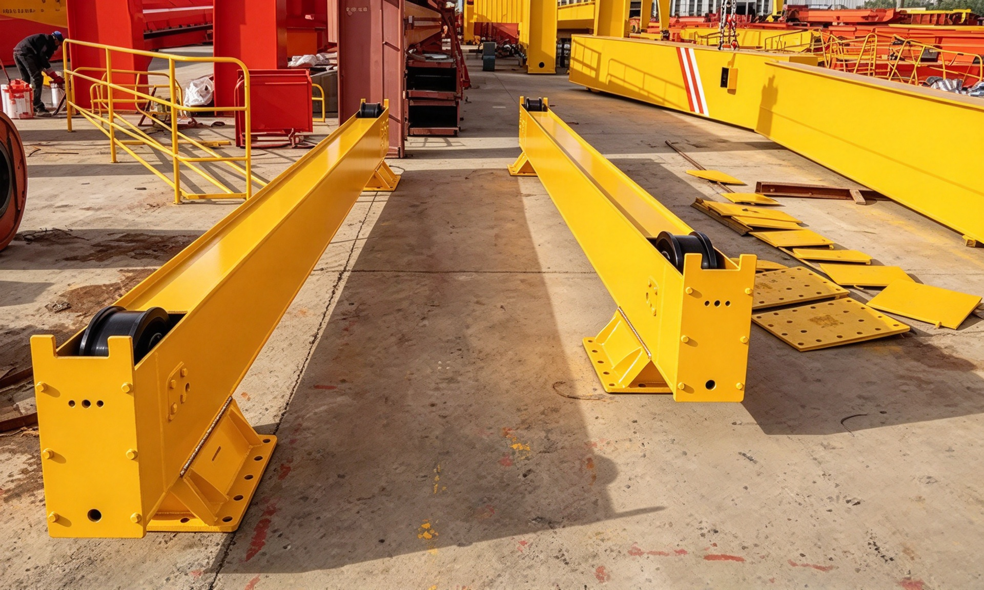
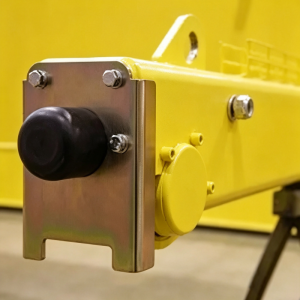
The ground beam connects the supporting structure to the crane travelling mechanism. It distributes operating loads to the wheels and runway while supporting stable longitudinal movement.
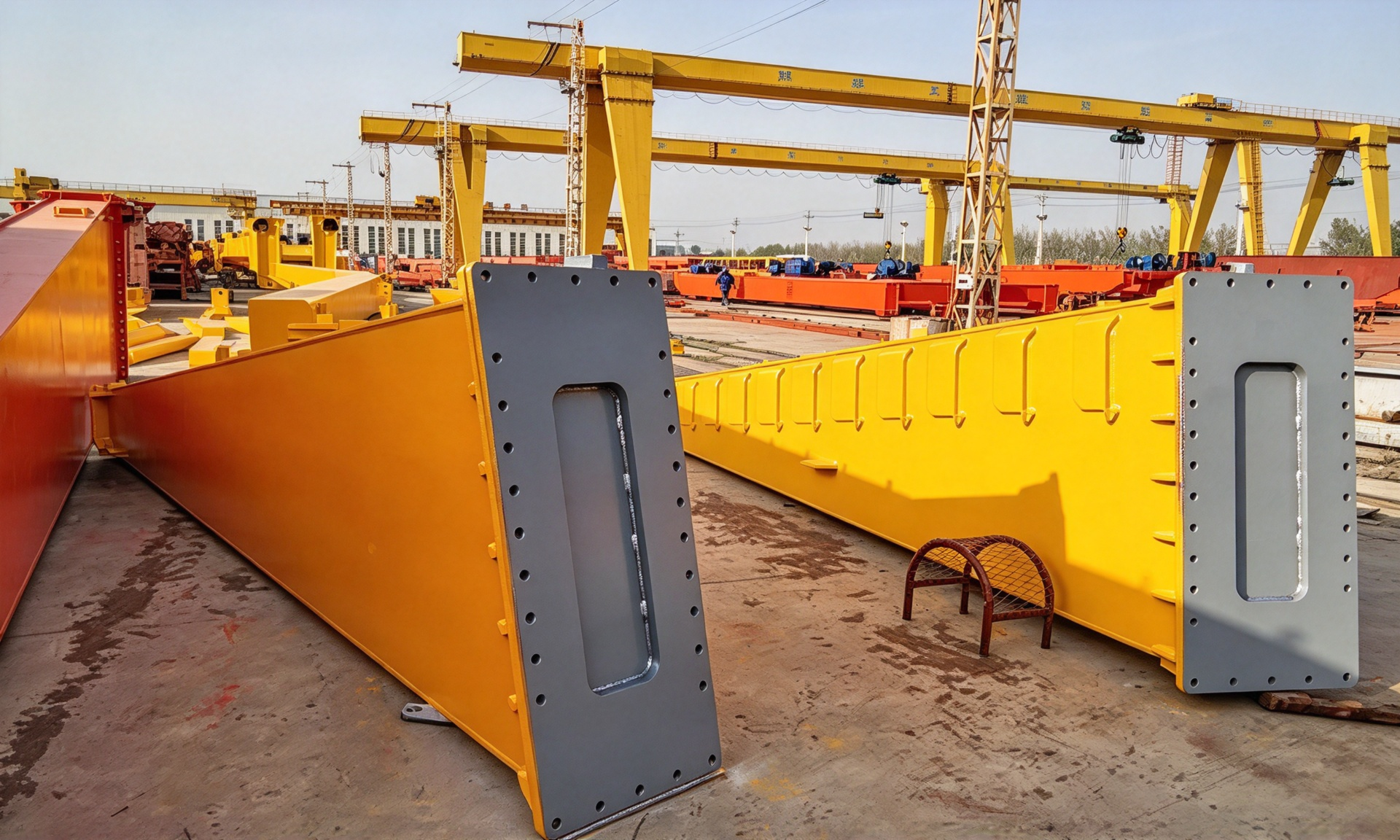
The support legs connect the main beam and ground beams to form the self-supporting gantry structure. Rigid or flexible-leg arrangements are selected according to the span, site conditions and structural requirements.
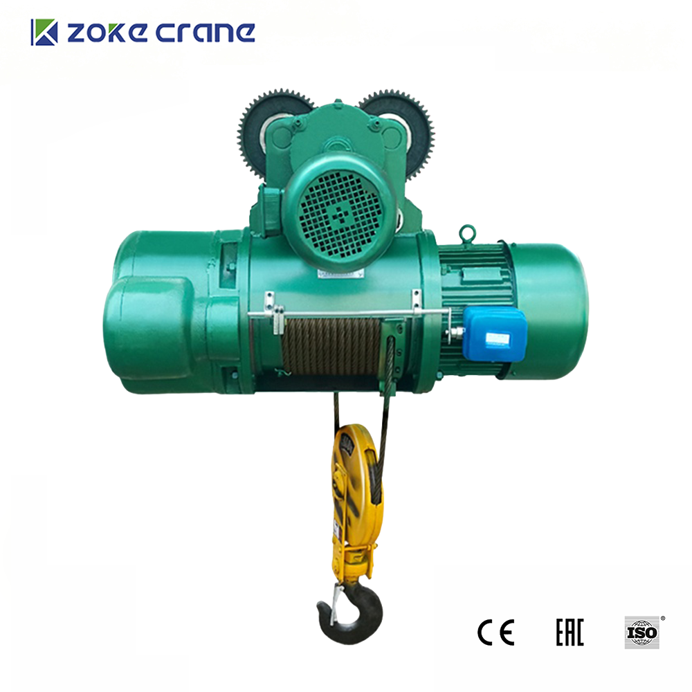
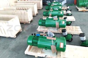
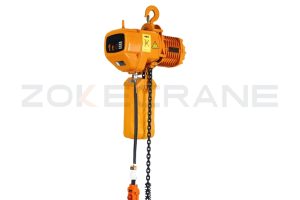
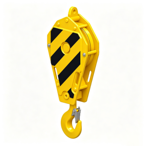
CD/MD electric wire rope hoists or electric chain hoists can be supplied for lifting and cross travel. Capacity, lifting height, speed, duty class and headroom are matched to the project.
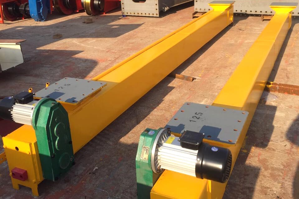
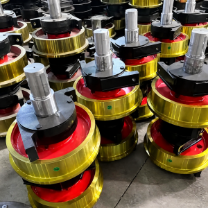
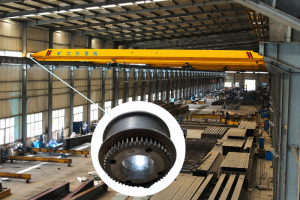
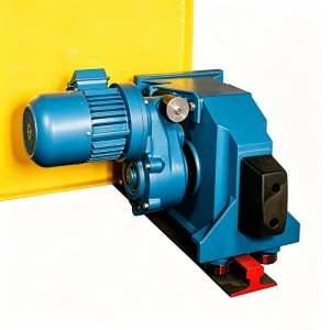
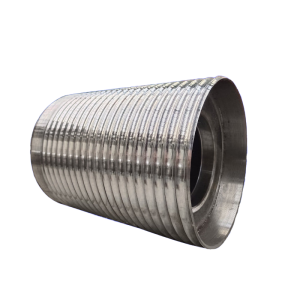
The travelling mechanism integrates motors, reducers, brakes and crane wheels for dependable long travel. Dual-side drive and optional variable-frequency control support smooth starting, stopping and positioning.
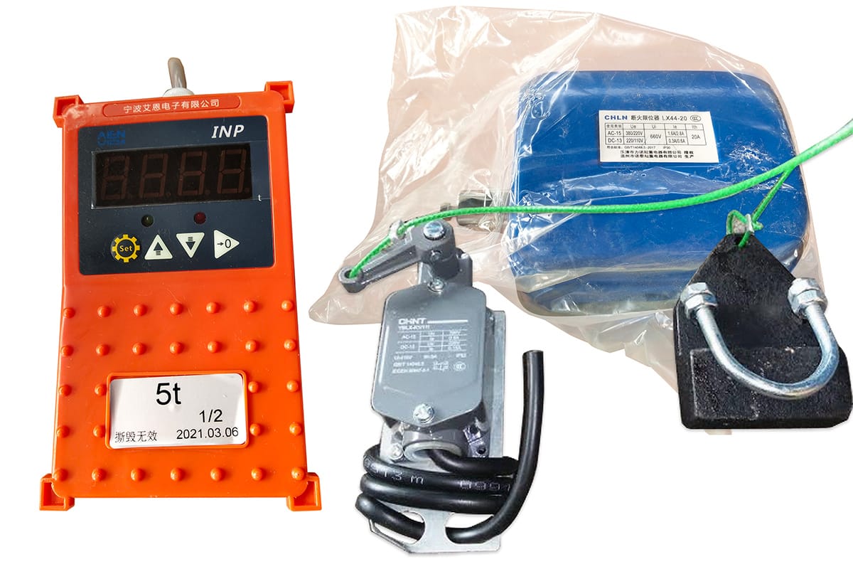
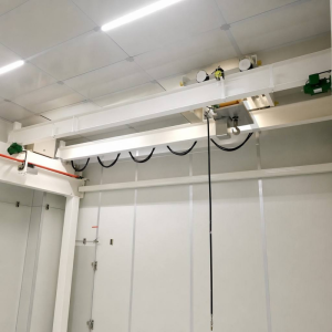
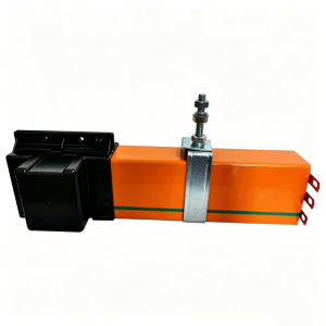
Festoon cable systems commonly supply the electric hoist, while cable reels or sliding contact lines can supply crane travel. The final arrangement is selected for the travel length, voltage and site environment.
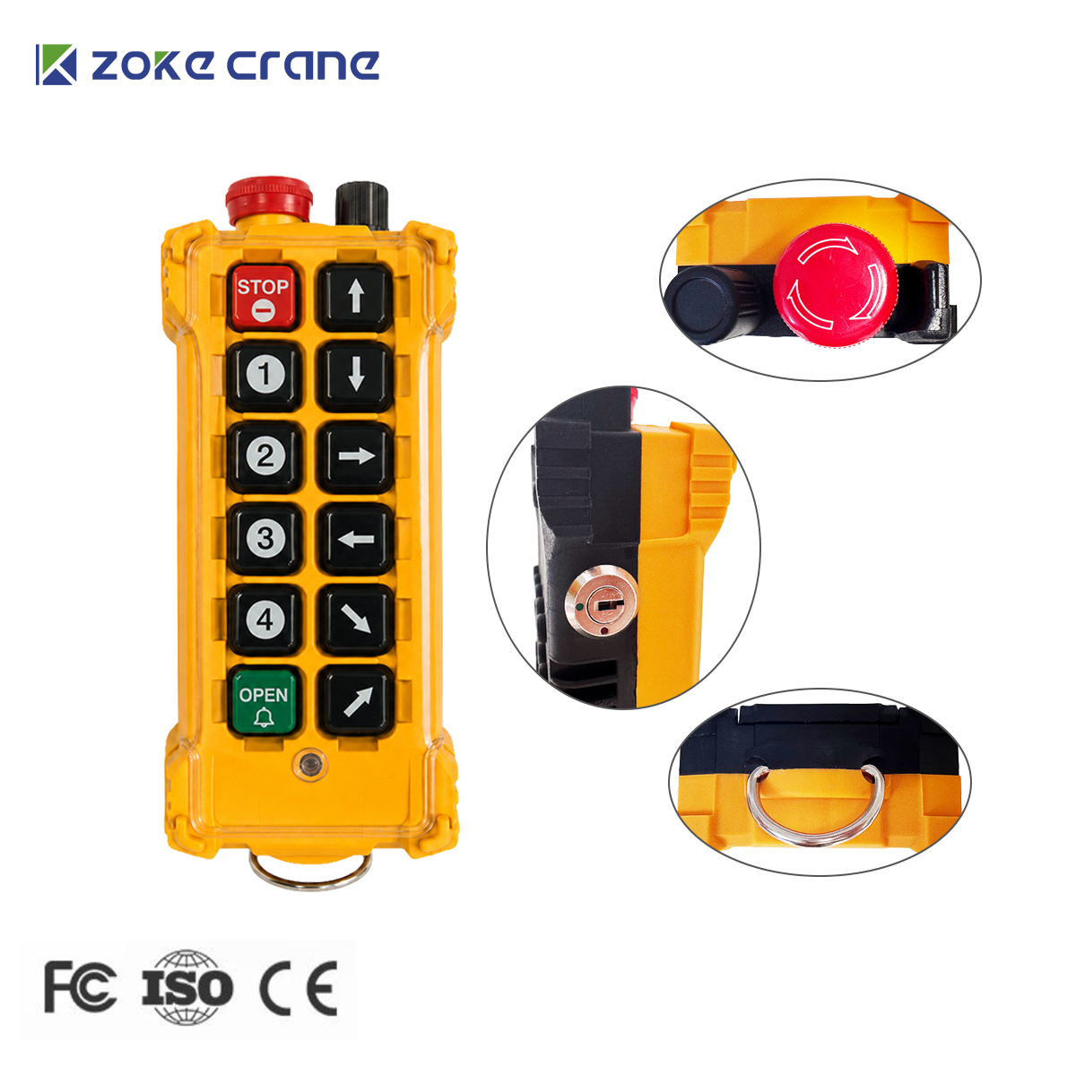
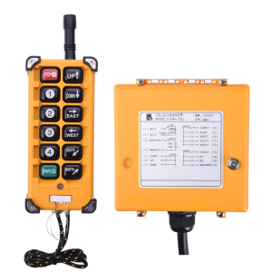
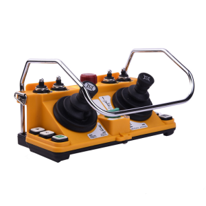
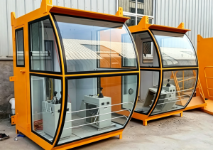
Pendant control and wireless remote control are standard options, with cabin control available when required. Emergency stop, electrical interlocks and low-voltage control can be configured for safe operation.
Please provide the rated capacity, span, lifting height, total travel length, power supply, control method, duty requirements and indoor or outdoor operating conditions. Photos or drawings of the installation area are also helpful.
Yes. The span, lifting height, overall height, cantilever length, travelling speed, hoist type and control system can be engineered for the project. Low-headroom, truss, European-style and semi-gantry configurations are available.
Yes. Outdoor cranes can be supplied with suitable paint systems, weather covers, rain protection and wind-protection devices. The site wind conditions and operating temperature should be confirmed before design.
CD1 or MD1 electric wire rope hoists are commonly used, while electric chain hoists and low-headroom hoists are available for specific capacities and clearance requirements. Single-speed, dual-speed and variable-frequency control can be selected.
Pendant control, wireless remote control and cabin control are available. The crane can be configured for common industrial voltages and frequencies, with cable reels, festoon systems or conductor lines selected according to the travel arrangement.
Typical protection includes overload limiting, upper and lower lifting limits, emergency stop, phase and voltage protection, travel limit switches, buffers and electrical interlocks. Anti-collision and wind-protection devices can be added when required.
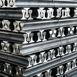
The rail gauge, travel length, ground bearing capacity and foundation conditions must be confirmed. ZOKE can provide crane and rail layout drawings, while the final civil foundation should be verified by a qualified local engineer.
The crane is pre-assembled and tested before shipment where practical. Installation drawings, electrical diagrams and remote guidance are provided, with on-site support available by agreement. The production schedule and warranty are confirmed in the final contract.
Share the capacity, span, lifting height, voltage and operating conditions. Our engineers will reply with a suitable solution within 24 hours.
The latest ZOKECRANE price list, news, articles, and resources.